Lab 1
This lab was mostly about familiarizing ourselves with the Artemis Nano board. The lab objectives were mostly simple tasks to ensure that our computer was able to upload code and communicate with the Nano board for future labs.
Objective 1
The first objective was to make the built-in LED on the Artemis Nano board blink. The IDE we used was the Arduino IDE. After we downloaded the proper support, we could upload the example code provided to us by SparkFun. I actually uploaded the Arduino “Blink” example for the video by accident, but both codes fortunately still worked. The nice bit was being able to use the digitalWrite() functions. Here is a video of me testing the “Blink” code for my Artemis Nano board:
Objective 2
The second objective was to test the serial communication between the Artemis board and our computers. For this objective, I uploaded the example code provided by SparkFun which created an “echo” machine that returned any string we input into the terminal, to the serial monitor. One important thing to note is that we had to change the baud rate to match the rate that was put into the code, which was 115200 in this case. Otherwise, we would get strange symbols instead of the desired output. This can be seen in the first line of the video. Here is a video of me testing this functionality:
Objective 3
The third objective was to test the ADCs (analog-to-digital converters) on the Artemis board. To do this, we utilized the on-board temperature sensors that are internally connected to a few of the ADC channels. We used an example program given to us by SparkFun, which used the built-in Arduino function analogRead(). The ADC outputs that the example code output to the serial monitor were
..* external (count), the analog voltage of the ADC pin
..* temp(counts), the raw temperature reading from the temperature sensor
..* vcc/3 (counts), the common collector voltage/3
..* vss(counts), Ground (which should always be 0 or something’s wrong with our circuit)
 It appears that the value returned is the raw 14-bit number returned by the ADC. Below is a video of me running the example code for the ADC:
Objective 4
The fourth objective was to test the PDM microphone. PDM stands for pulse density modulation, which is a way to represent an analog signal, such as a frequency signal, in binary. Essentially, an electrical signal switches and the faster the signal switches, the greater the value.We used an example code file provided by SparkFun, which utilized an extra math library to perform a FFT on the data as well. Below is a video of me testing the microphone by whistling to a higher frequency:
MEng Objective
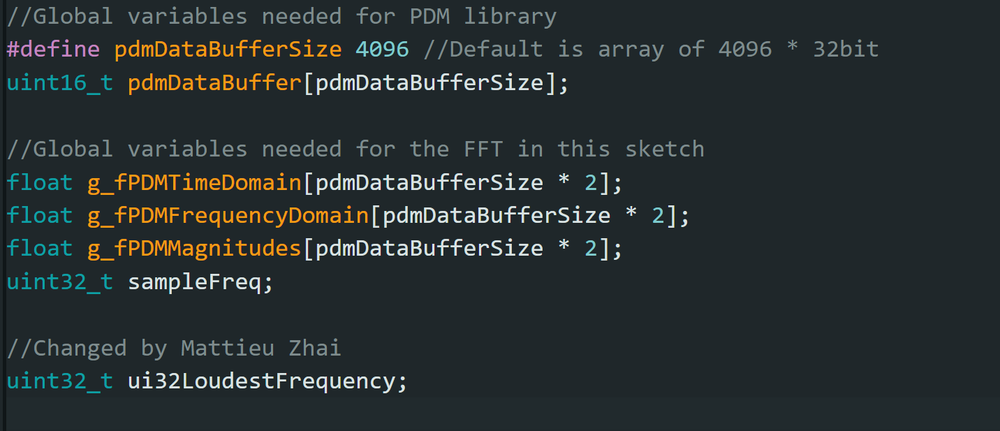
The extra task given to MEng students was to make the LED light up whenever a musical A was played. To fulfill this task, I decided to tune to A-220. The first change I made was to take the variable which was used to store the loudest frequency and turn it into a global variable so that every part of the code could access it:
 After that, since I knew that every octave traditionally means the frequency goes up/down by a factor of 2, I decided to create an if/else statement that would light up the LED if the loudest frequency was a multiple of 220 Hz, which would also mean the note is an A. I utilized the modulo operator so that I could test for all multiples of 220. I also created a little buffer zone to account for some errors.
 Here is a video of me testing this functionality and proving it works: