Lab 4
The purpose of this lab was to get the IMU working, set up our batteries so we can power our Artemis without having it connected to our laptop, and also start playing with our robot car and make sure that we can get some sensor readings while our robot is driving around.
Setting Up the IMU
In order to be able to use the IMU (SparkFun SEN-15335), we had to install the relevant Arduino library, SparkFun 9 DOF IMU Breakout - ICM20948. To use the example code, I connected the IMU to the QWIIC port on the actual Artemis board so that there wouldn’t be any other I2C devices on the peripheral.
Photo of my setup originally:
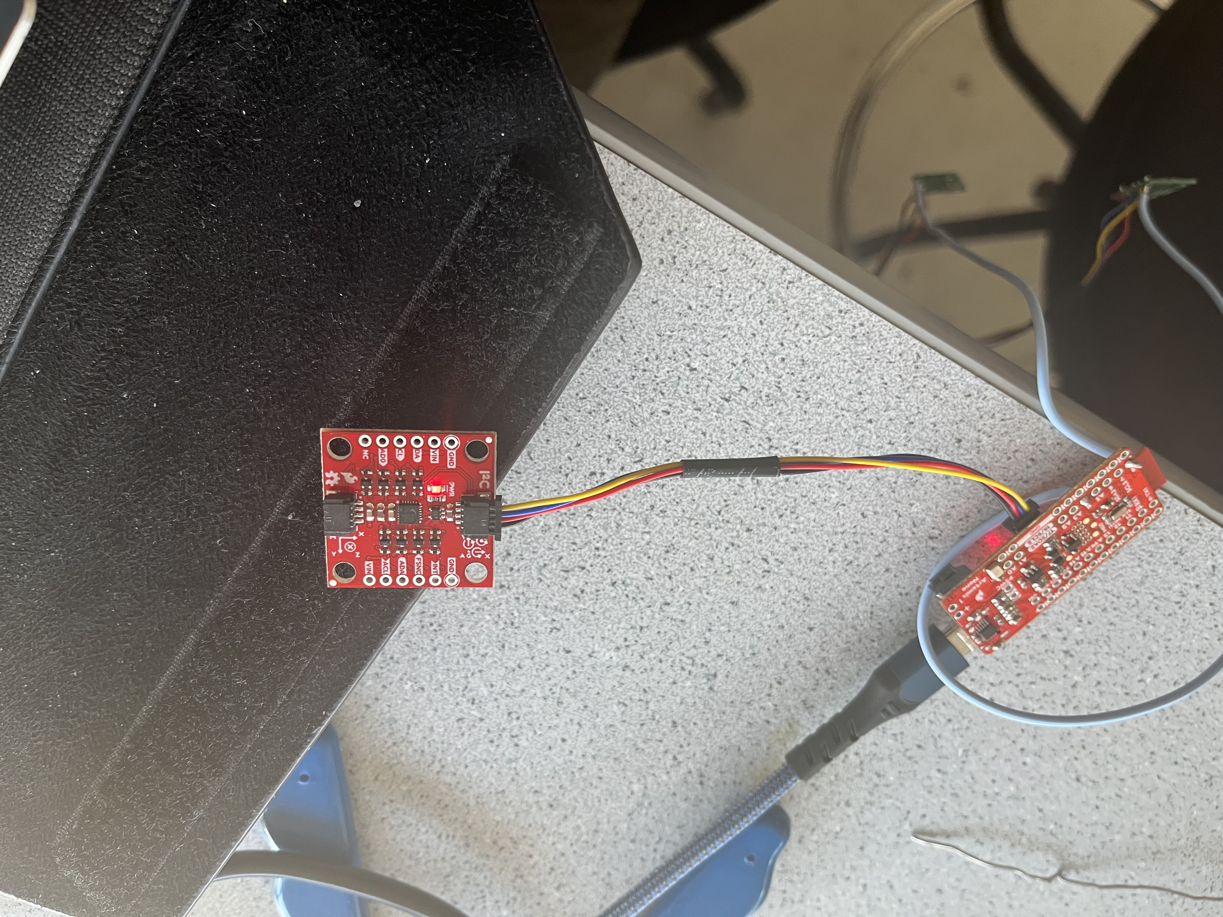
After I connected it, I ran the Arduino example given to us with the Arduino library to make sure that the IMU was working (Example1_Basics.ino)
Serial Output:

In the data that the example prints, it seems that a lot of the values are scaled down by the example code. Other than that, the values were printed as predicted. The axes are defined on the IMU breakout board so it was easy to alter the values I wanted. The only thing that was of note is that the IMU could pick up on the Earth’s graviational acceleration in the z-axis.
Video of SerialPlot plotting accelerometer data:
In the example, an AD0_val is defined. This value determines the least significant bit (LSB) of the IMU’s I2C address. This means that we can use two IMUs in parallel if we have the logic value of that pin different on both IMUs. By default, the value is 0 when the ADR jumper is closed, which it should be by default. However, this doesn’t really matter for us because we’re only using one IMU.
Accelerometer Data for Pitch and Roll
In order to use the accelerometer data for pitch and roll, we used the equations that were given to us:
\[\theta = tan^{-1}(a_x/a_z) = atan2(a_x/a_z)\] \[\phi = tan^{-1}(a_y/a_z) = atan2(a_y/a_z)\]Note that we use the built-in atan2 function to get the correct outputs that we want (-1 to 1 radians), which we can convert to degrees. We tested both pitch and roll (note that you cannot calculate yaw using the accelerometer data).
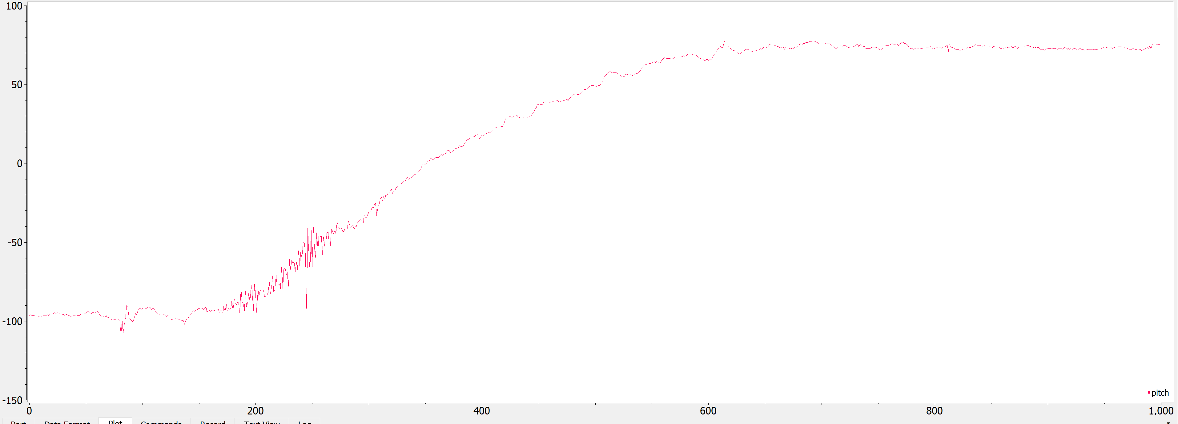
Below is a photo of pitch when I turned it from -90 to 90 degrees along the y-axis:
Below is a photo of roll when I turned it from -90 to 90 degrees along the x-axis:
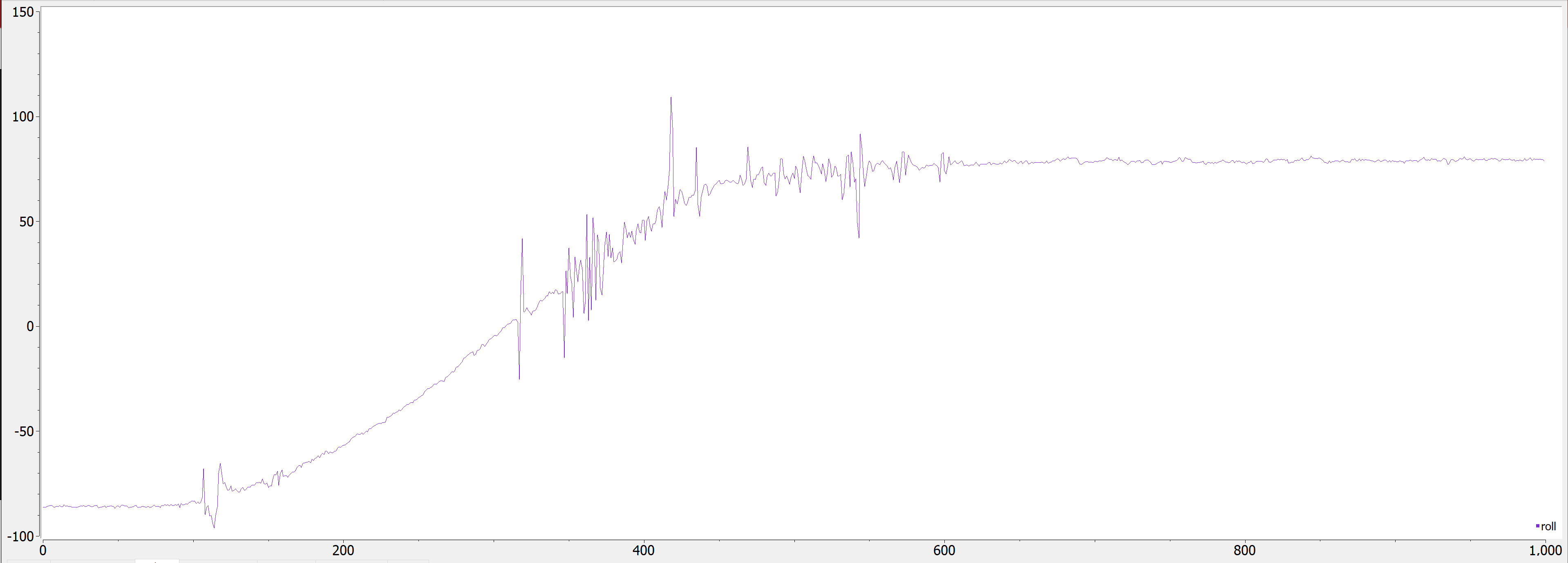
As we can see, there is a decent amount of noise within the data, though it is pretty accurate. Because of its accuracy, I decided not to do a two-point calibration.
Arduino code:
pitch_a = atan2(myICM.accX(),myICM.accZ())*180/M_PI;
roll_a  = atan2(myICM.accY(),myICM.accZ())*180/M_PI;
Serial.print(pitch_a);
Serial.print(", ");
Serial.print(roll_a);
Serial.println();
Fourier Transform
In order to try to remove noise by designing a good low-pass filter, I performed a Fast Fourier Transform on both the pitch and roll data in Python.
Graph:
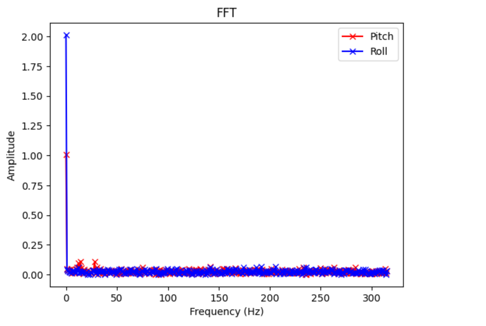
I sampled 630 samples in 2 seconds, so I analyzed up to 315 Hz. As we can see (disregarding the spike at 0 Hz), we can’t really see any spikes in the transform. I ignored the tiny spikes in the pitch data at 13 Hz and 27 Hz, as I assumed those were not real spikes. This is expected, as there is already a low-pass filter built into the IMU’s breakout board.
Gyroscope for Pitch and Roll
To use the gyroscope to find pitch, roll, and yaw, we essentially integrated the gyroscope data in discrete time steps (our sampling time)
Equations:
\[\theta = \theta + {\omega}_x * {\delta} t\] \[\phi = \phi + {\omega}_y * {\delta}t\] \[\psi = \psi + {\omega}_z * {\delta}t\]Here is a video of the pitch, roll, and yaw values (sorry might need to up brightness):
As we can see, there is noticeable drift in the values. In the video, we can see that the lines are all over the place. Here is a photo showing more drift when I left it laying flat for a few minutes:
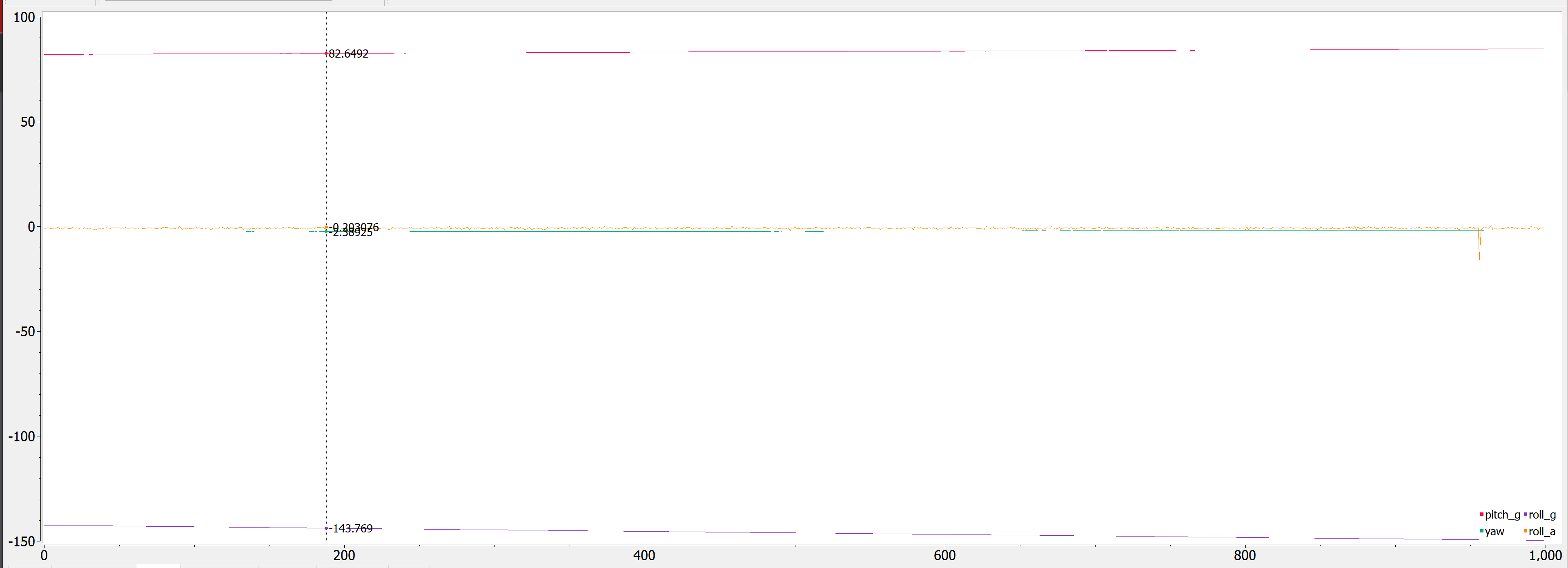
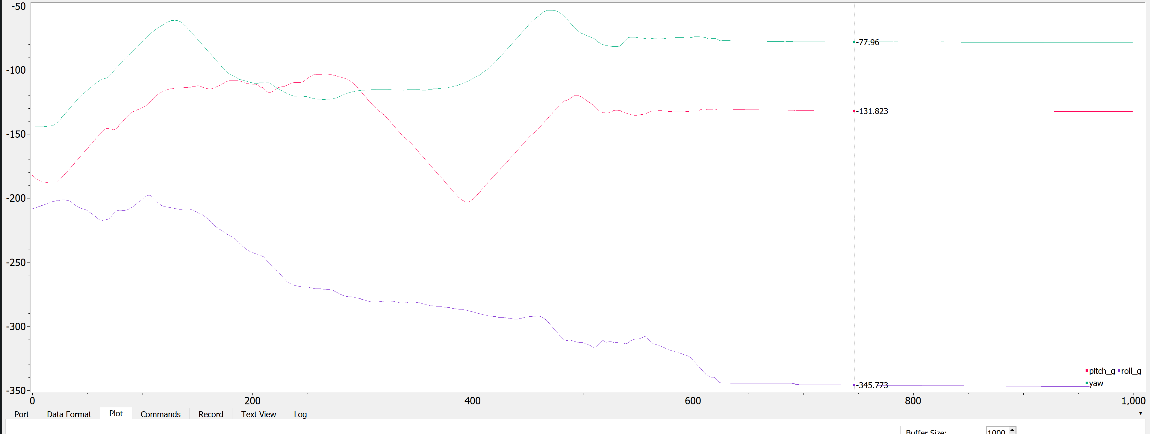
In order to see what effect sampling rate would have on drift, I added a few delay() statements to my Arduino code and then plotted pitch, roll, and yaw:
delay(10);
delay(100);
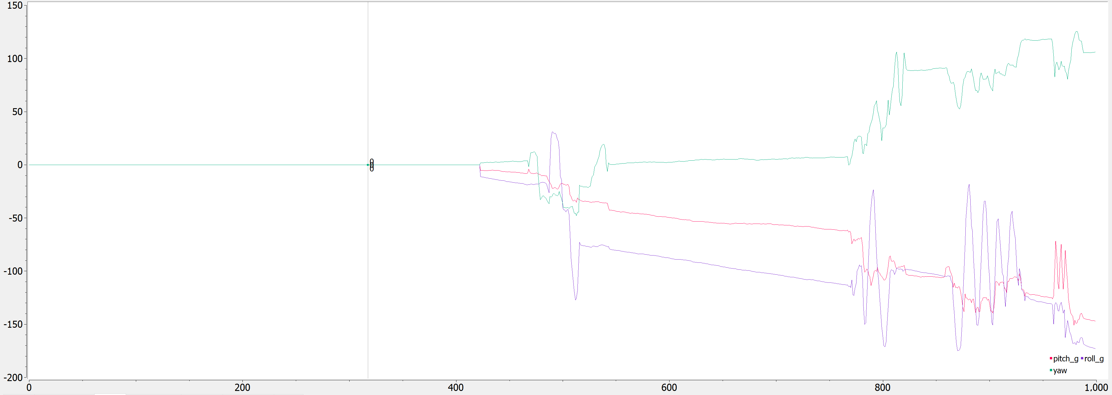
With delay(10), it drifted faster but still give some sensible outputs. With delay(100), it was all over the place. Thus, with a higher sampling frequency, the data becomes more accurate with less drift.
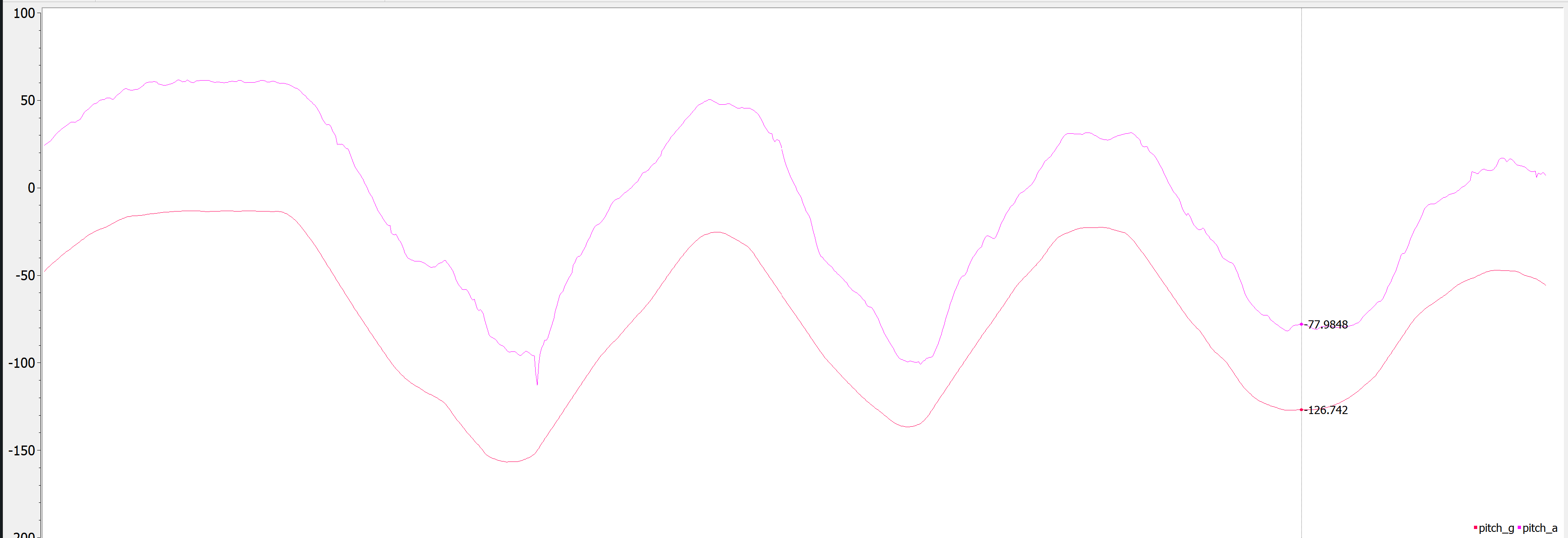
I also compared these values to a filtered output of pitch and roll from the accelerometer. Because our frequency analysis yielded nothing, I decided to use an \(\alpha\) of 0.2, which correlates to a cutoff frequency of about 15 Hz.
Comparison to filtered pitch:
Comparison to filtered roll:
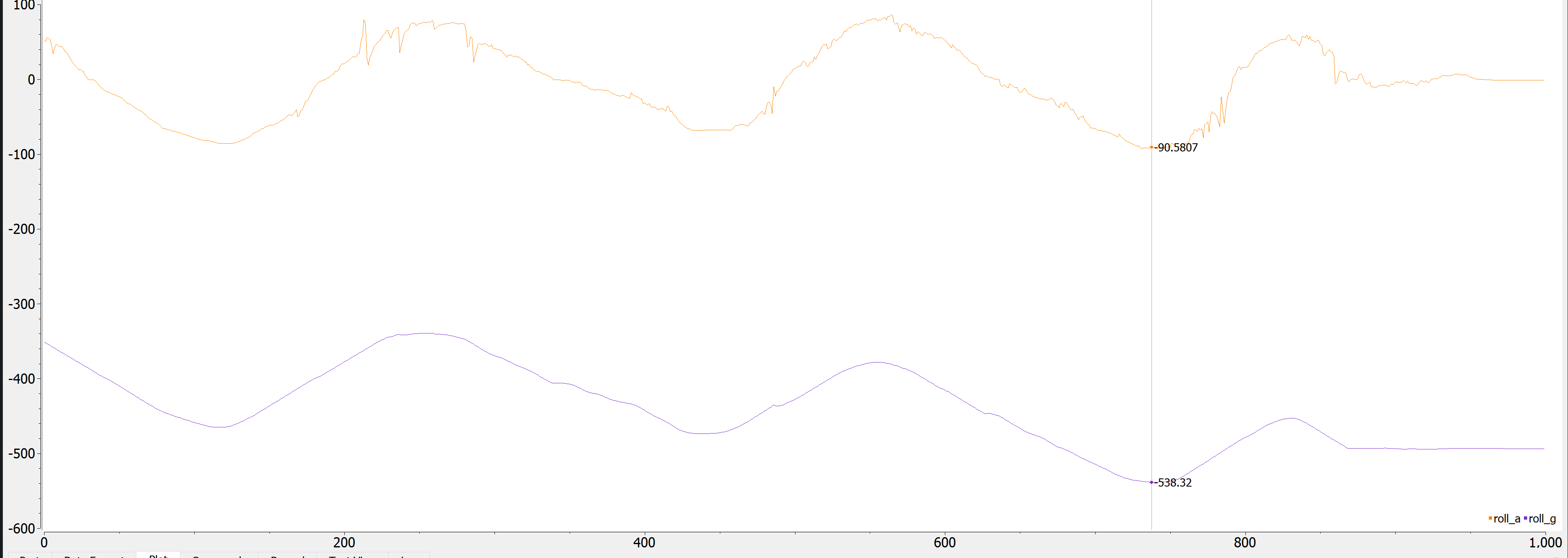
From this, we see that the values calculated from the accelerometer are more accurate, but more noisy, while the values from the gyroscope are less noisy, but also less accurate.
Arduino code:
const float alpha = 0.2;
dt = (micros()-last_time)/1000000.;
last_time = micros();
pitch_g = pitch_g + myICM.gyrY()*dt;
roll_g = roll_g + myICM.gyrX()*dt;
yaw_g = yaw_g + myICM.gyrZ()*dt;
Serial.print(-1 *pitch_g);
Serial.print(", ");
Serial.print(roll_g);
Serial.print(", ");
Serial.println(yaw_g);
Serial.print(", ");
roll_a = atan2(myICM.accY(),myICM.accZ())*180/M_PI;
roll_a_LPF[n] = alpha *roll_a + (1-alpha) * roll_a_LPF[n-1];
roll_a_LPF[n-1] = roll_a_LPF[n];
Serial.print(roll_a_LPF[n]);
Serial.print(",");
pitch_a = atan2(myICM.accX(),myICM.accZ())*180/M_PI;
pitch_a_LPF[n] = alpha*pitch_a + (1-alpha)*pitch_a_LPF[n-1];
pitch_a_LPF[n-1] = pitch_a_LPF[n];
Serial.print(pitch_a_LPF[n]);
Serial.println();
Complimentary Filter
In order to get the best of both world, we can use a complimentary filter. The equation is as follows:
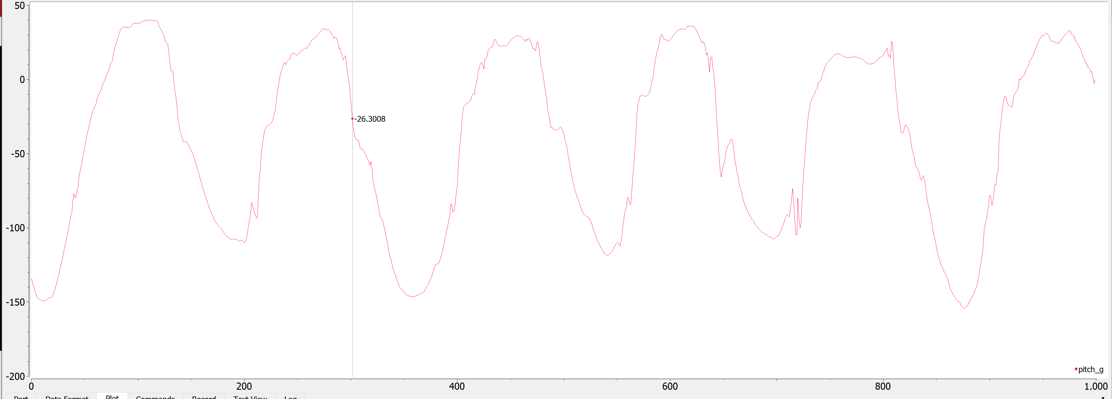
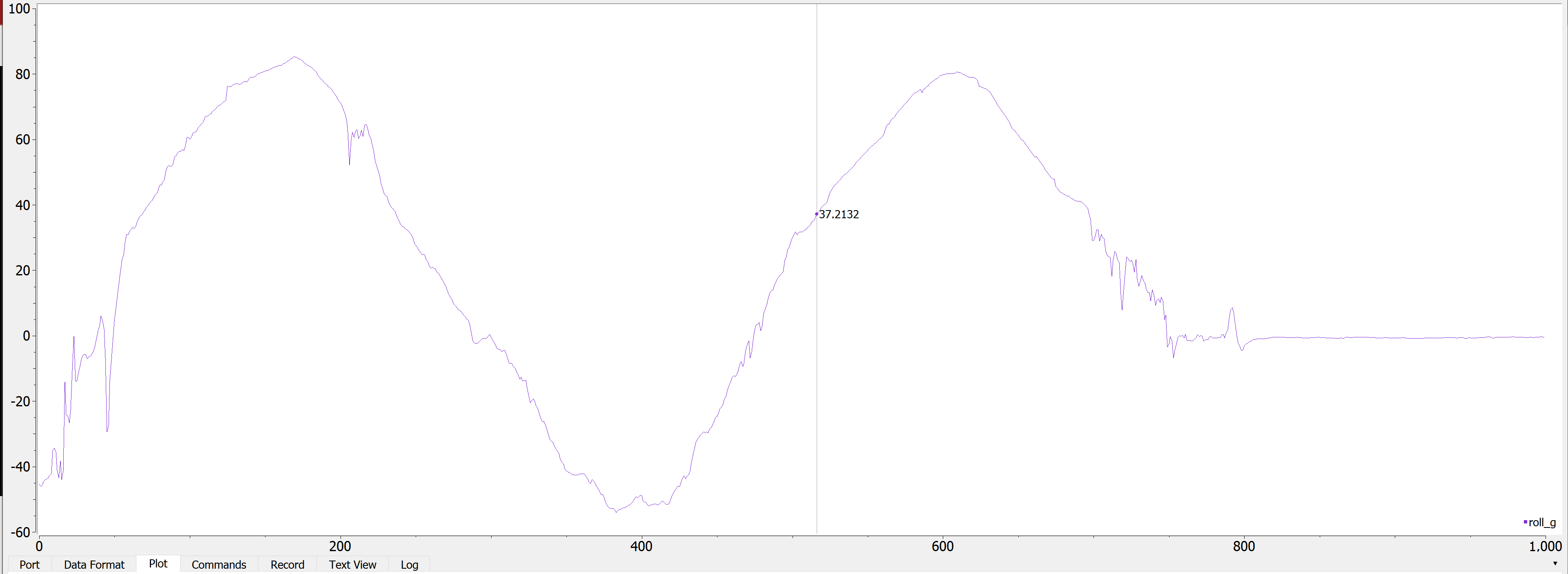
\[\theta = (\theta + {\omega}_x * dt)(1 - \alpha) + a_x * \alpha\] \[\phi = (\phi + {\omega}_y * dt)(1 - \alpha) + a_y * \alpha\]I used an alpha of 0.2 because I wanted less noise. I noted that it was still pretty accurate around -90 and 90 degrees, though not as accurate as just the accelerometer. However, it was definitely smoother (note the graphs do not show exactly -90 to 90 degrees, I was just twisting it for the screenshot).
Complimentary filtered pitch
Complimentary filtered roll
Arduino Code:
pitch_a = atan2(myICM.accX(),myICM.accZ())*180/M_PI;
dt = (micros()-last_time)/1000000.;
last_time = micros();
pitch_g = pitch_g + myICM.gyrY()*dt;
pitch = (pitch+myICM.gyrY()*dt)*0.8 + pitch_a*0.2;
Serial.print(pitch);
Serial.print(", ");
roll_a  = atan2(myICM.accY(),myICM.accZ())*180/M_PI;
roll_g = roll_g + myICM.gyrX()*dt;
roll = (roll+myICM.gyrX()*dt)*0.8 + roll_a*0.2;
Serial.print(roll);
Serial.println();
Sampling IMU Data
I added some micros() function calls to calculate how quick I could sample the code. I connected the IMU to the QWIIC breakout board and then attached it to the Artemis to simulate how it’s gonna be on the robot. I got that it could sample within 1.768 ms.
Serial Output (note I placed the Serial.print statements outside of the time measurements)

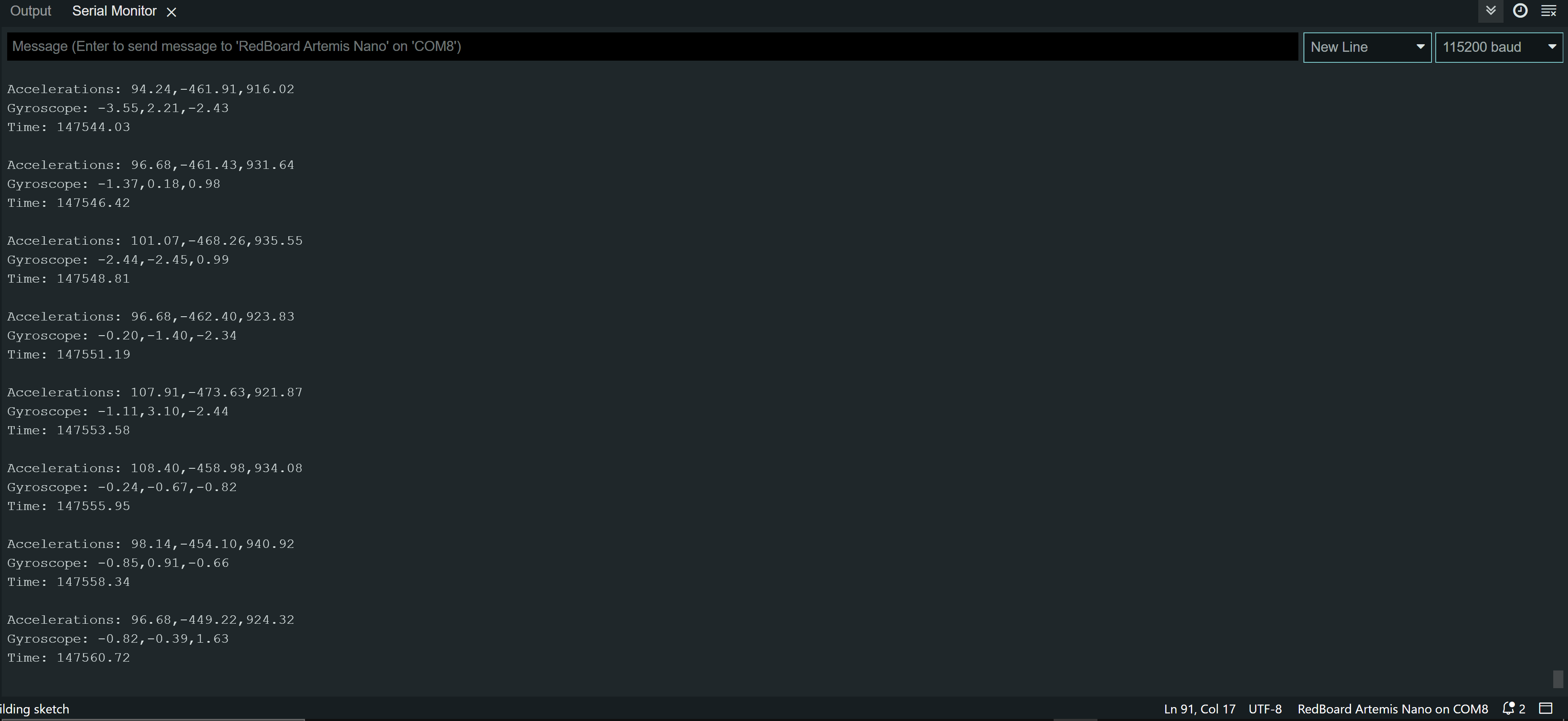
I then wrote some code to store the values into float arrays. For this one, I allocated 100 floats to each array.
Here is the Arduino code + print statements to prove it worked:
while(count < 100){
    if(myICM.dataReady()){
      myICM.getAGMT();
      times[count] = micros()/1000.;
      accX[count] = myICM.accX();
      accY[count] = myICM.accY();
      accZ[count] = myICM.accZ();
      gyrX[count] = myICM.gyrX();
      gyrY[count] = myICM.gyrY();
      gyrZ[count] = myICM.gyrZ();
      count = count + 1;
    }
  }
  count = 0;
  for(int i = 0; i < 100; i++){
    Serial.print("Accelerations: ");
    Serial.print(accX[i]);
    Serial.print(",");
    Serial.print(accY[i]);
    Serial.print(",");
    Serial.println(accZ[i]);
    Serial.print("Gyroscope: ");
    Serial.print(gyrX[i]);
    Serial.print(",");
    Serial.print(gyrY[i]);
    Serial.print(",");
    Serial.println(gyrZ[i]);
    Serial.print("Time: ");
    Serial.println(times[i]);
    Serial.println();
  }
  delay(5000);
And the Serial output:
Finally, I attempted to send 5 seconds of data back over Bluetooth, including ToF data. This time, I measured 500 values as fast as possible. I only checked to see if the ToF sensor data was ready because I knew that it was slower than the IMU so if the ToF data was ready, the IMU data would most likely be ready too (also IMU is less buggy when not checking to see if its data is ready). I then used a notification handler to extract the values and plotted them. I tested it while stationary.
Arduino code:
case GET_DATA:
          Serial.println("Started");
          distanceSensor1.setDistanceModeLong();
          distanceSensor2.setDistanceModeLong();
          start_time = micros()/1000.;
          count = 0;
          while(count < size){
            if(distanceSensor1.checkForDataReady() && distanceSensor2.checkForDataReady()){
            //if(myICM.dataReady()){
                myICM.getAGMT();
                t[count] = micros()/1000.;
                d1s[count] = distanceSensor1.getDistance();
                d2s[count] = distanceSensor2.getDistance();

                myICM.getAGMT();
                accX[count] = myICM.accX();
                accY[count] = myICM.accY();
                accZ[count] = myICM.accZ();
                gyrX[count] = myICM.gyrX();
                gyrY[count] = myICM.gyrY();
                gyrZ[count] = myICM.gyrZ();
                count = count + 1;
            }
            //}
          }
          for(int i = 0; i < size; i++){
            tx_estring_value.clear();
            tx_estring_value.append("T:");
            tx_estring_value.append(t[i]);
            tx_estring_value.append("|D1:");
            tx_estring_value.append(d1s[i]);
            tx_estring_value.append("|D2:");
            tx_estring_value.append(d2s[i]);
            tx_estring_value.append("|AX:");
            tx_estring_value.append(accX[i]);
            tx_estring_value.append("|AY:");
            tx_estring_value.append(accY[i]);
            tx_estring_value.append("|AZ:");
            tx_estring_value.append(accZ[i]);
            tx_estring_value.append("|GX:");
            tx_estring_value.append(gyrX[i]);
            tx_estring_value.append("|GY:");
            tx_estring_value.append(gyrY[i]);
            tx_estring_value.append("|GZ:");
            tx_estring_value.append(gyrZ[i]);
            tx_estring_value.append("|");
            tx_characteristic_string.writeValue(tx_estring_value.c_str());
          }
            Serial.println("Finished");
          break;
Notification handler:
#Extracting the values with the notification handler
times = []
d1 = []
d2 = []
ax = []
ay = []
az = []
gx = []
gy = []
gz = []
global times
global d1
global d2
global ax
global ay
global az
global gx
global gy
global gz

def extract_distances(uuid, data):
    temps = ble.bytearray_to_string(data);
    temps = temps.split("|");
    temps.pop();
    for i in temps:
        if(i[0] == "T"):
            times.append(float(i[2:]));
        if(i[0] == "D" and i[1] == "1"):
            d1.append(float(i[3:]));
        if(i[0] == "D" and i[1] == "2"):
            d2.append(float(i[3:]));
        if(i[0] == "A" and i[1] == "X"):
            ax.append(float(i[3:]));
        if(i[0] == "A" and i[1] == "Y"):
            ay.append(float(i[3:]));
        if(i[0] == "A" and i[1] == "Z"):
            az.append(float(i[3:]));
        if(i[0] == "G" and i[1] == "X"):
            gx.append(float(i[3:]));
        if(i[0] == "G" and i[1] == "Y"):
            gy.append(float(i[3:]));
        if(i[0] == "G" and i[1] == "Z"):
            gz.append(float(i[3:]));
ble.start_notify(ble.uuid['RX_STRING'], extract_distances)

ble.send_command(CMD.GET_DATA, "")
Distance plot:

Accelerometer plot:

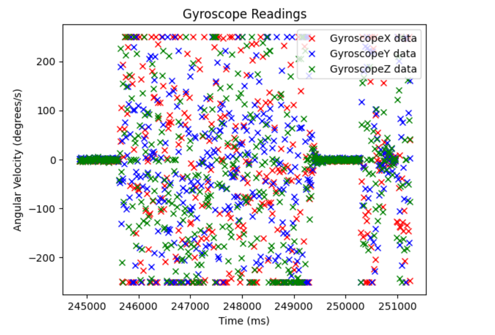
Gyroscope plot:

Cut the Coord
We have a 650 mAh and an 850 mAh battery because we want to use two different power supplys for the motor drivers and everything else. This is mainly because the motor drivers will draw a lot of power, so we need a battery that can output a lot of amperage. Having two batteries also means we can run our robot longer since the Artemis and sensors won’t be drawing power from the same power supply as the motors. This also reduces noise, as the motor drivers will introduce a lot of noise to our sensors and de-coupling them from the power supply allows us to eliminate some noise.
Here is a photo of my Artemis running with the battery:

Car Time!
I first drove the car around a bit. It feels like this car is really fast and just goes around really quickly. The turns are abrupt and appear to just turn the wheels at the same velocity in opposite directions to do a point turn. I was able to get it to flip consistently. Overall, very fast car.
Here is a video of me driving the car around without the Artemis:
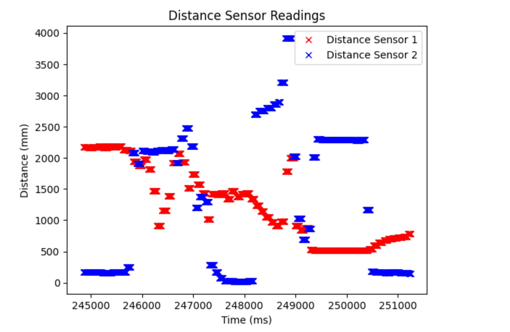
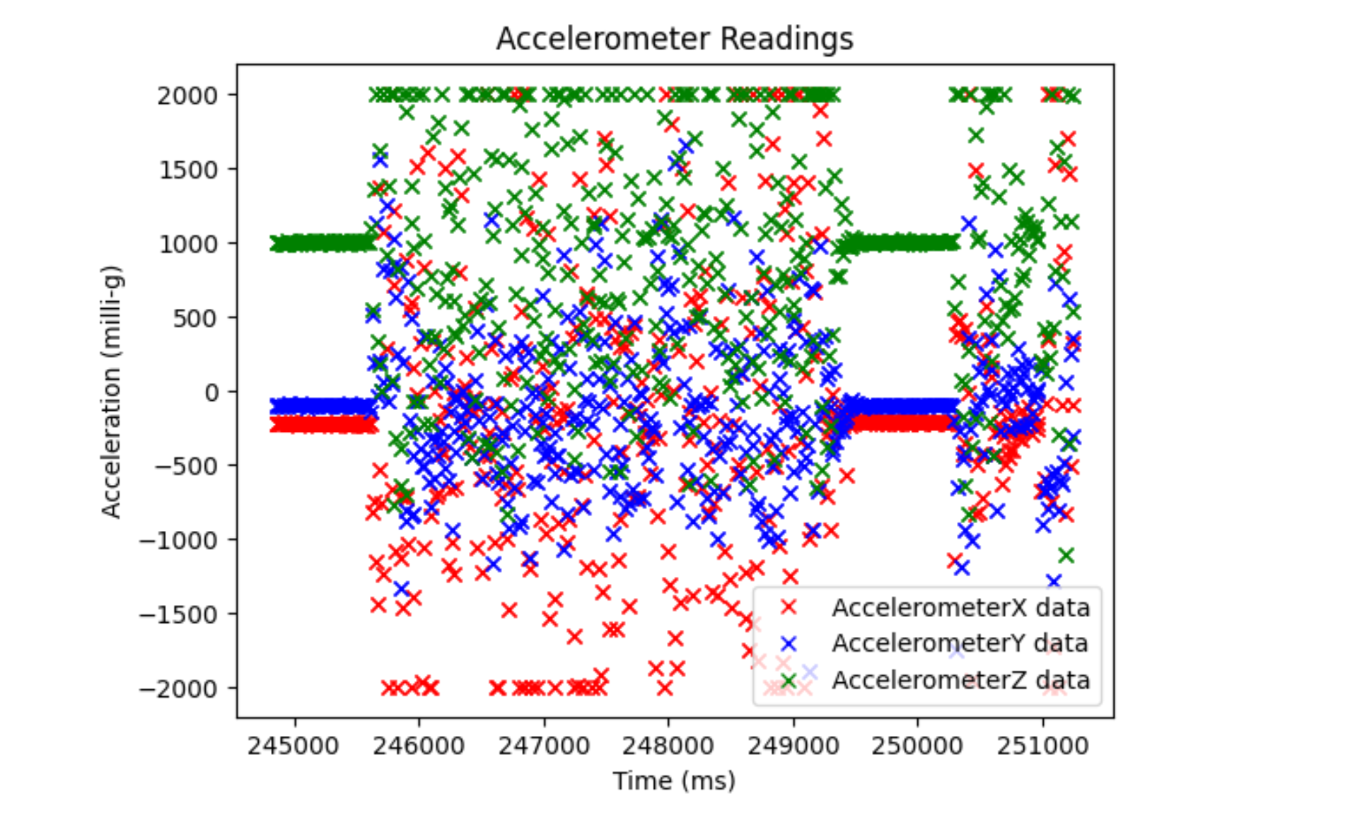
And here is the video of me driving the car with the Artemis. Note that I chose a slower stunt because I broke two wires doing a flip off a wall and had to re-solder it.
Distance plot:
Accelerometer plot:
Gyroscope plot:
