Lab 5
The objective of this lab was to connect new motor drivers to our robot, assemble all of our sensors onto our robot, and demonstrate open-loop control of the robot from the Artemis.
Diagram
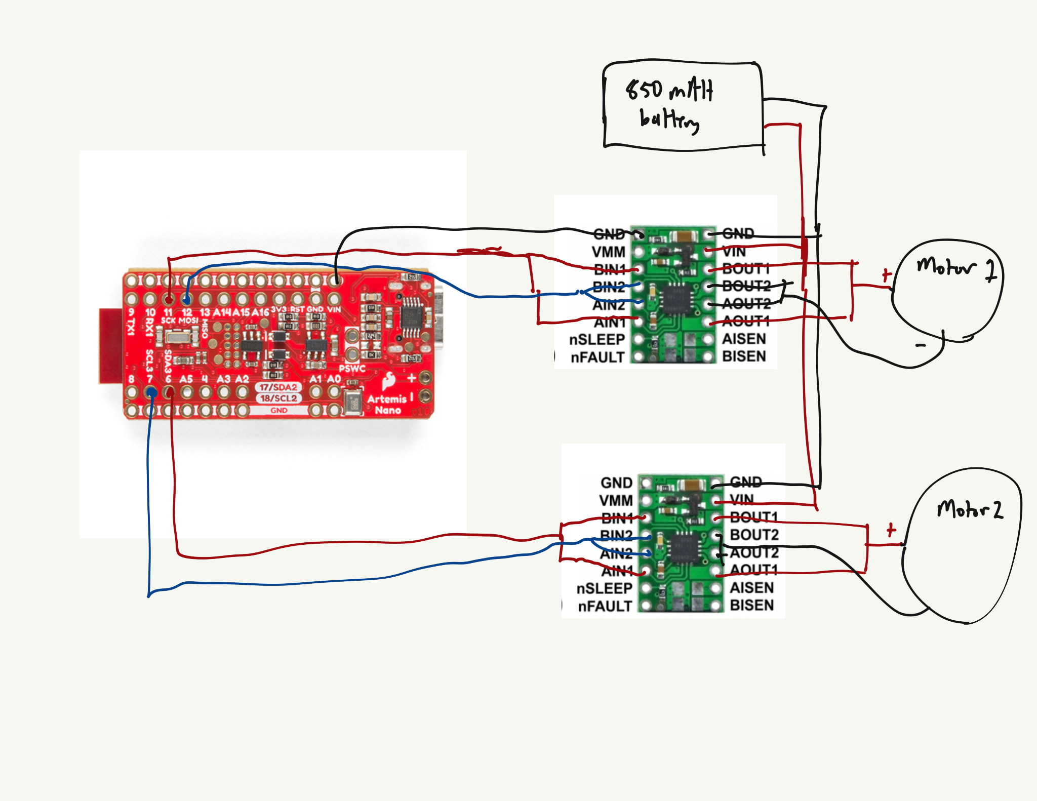
Here is a diagram of how I wired up my motor drivers to the Artemis, batteries, and motors. I connected the 850 mAh battery to the motors instead of the given 650 mAh battery. I did this because the motors use a lot more power than the Artemis/sensors ever will, so they get the 650 mAh battery. Separating the power sources also allows for less noise, as the motor drivers generate a lot of noise.

Testing the motor driver
After I soldered the wires to my motor driver and soldered the motor driver to my Artemis, I tested my motor driver output using a power supply and an oscillioscope. I forgot to take a photo of the setup (and now everything is connected to my robot), so here’s a verbal description instead. I attached the power supply to the Vin and GND wires. I measured the output from the A/BOUT1 pins and the A/BOUT2 wire with the oscilloscope probes (I attached the probe to the A/BOUT1 wire and the ground clip to the A/BOUT2 wire)
For the power supply, I used an output of 3.7 V to match our battery. I also set the current output to 1.2 A to match the current output that was suggested on the datasheet. The code I used to test the output is below:
void setup(){
  pinMode(6, OUTPUT); //1
  pinMode(7, OUTPUT); //2
}
void loop(){
    analogWrite(6, 128);
    analogWrite(7,0);

    delay(5000);

    analogWrite(6, 0);
    analogWrite(7,128);
}
I used this in order to test the forward and backwards functionality of the motor drivers. I should get two square waves that are the inverse of each other. Here is a video showing that it works both ways:
Note that the sawtooth wave is most likely due to some capacitance with the power supply or oscilloscope. When I tested it with a battery, I was able to see both square waves as expected.
Next, I connected the motor driver to a motor to test it’s spinning. I used the same code. Here is a video of the wheels spinning:
Afterwards, I connected the motor driver to a battery and ran the same code again. Here is the output with both square waves:
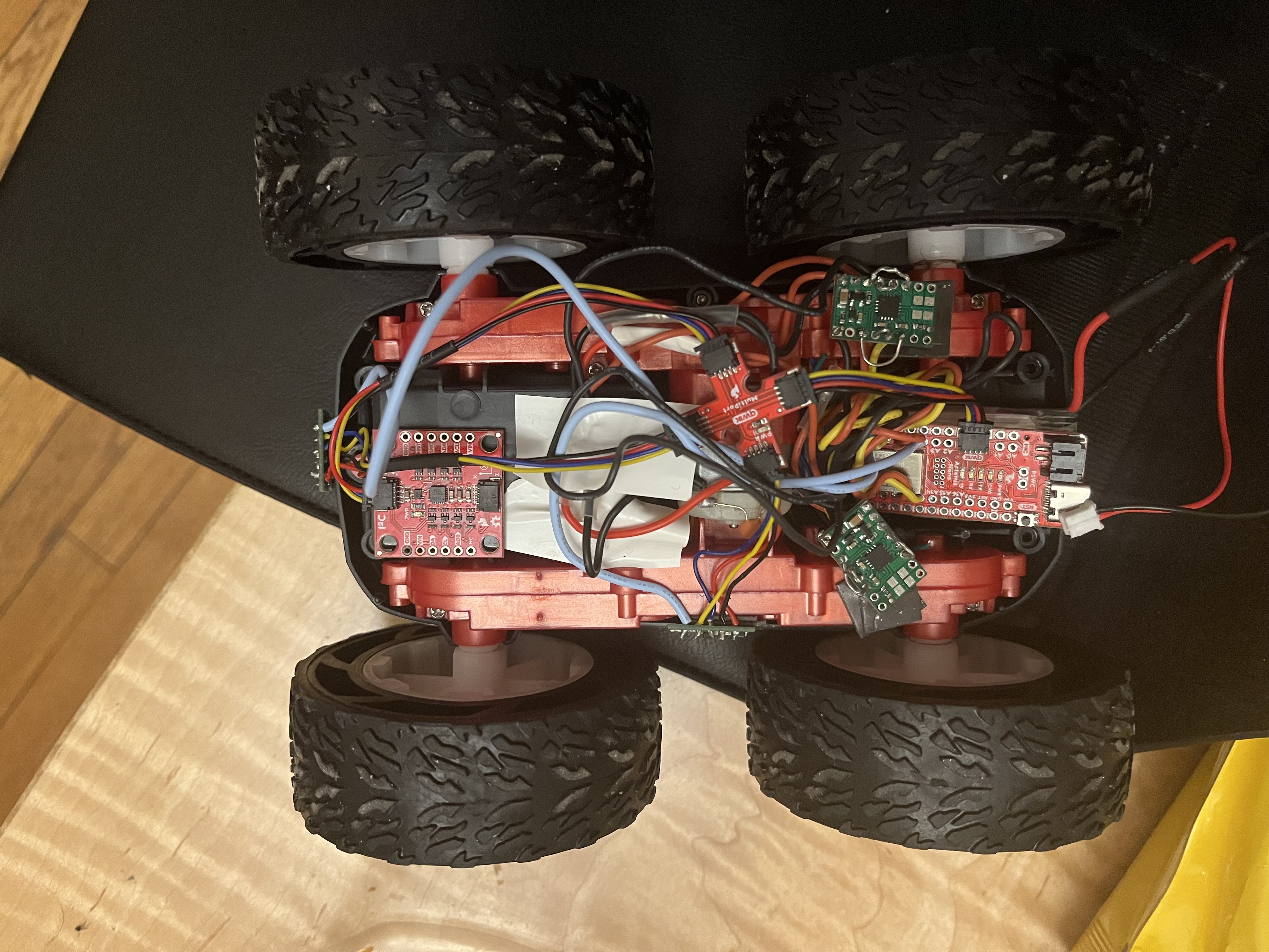
When I ensured that one motor was working, I connected the other and ran through the same process (it looked the same as when I did the first motor driver) After I had everything soldered and in a closed circuit with the battery, I attached my Artemis and sensors to the robot. I placed a ToF sensor at the front and one to the left (follow the blue wires to find them). The IMU is near the front of the car as well (to be as far away from the motor drivers as possible) Here is a photo of the setup:

After this, I started trying to make my robot move. I first explored the lower PWM values (which set the duty cycle) which would start my car from rest. I found that each motor had a different minimum PWM value. One motor driver only needed a PWM value of 41, while the other one could have a PWM value of 30. The motor that controls my left wheels needs a stronger signal than the one to my right. Here is the test code:
void loop() {
  //Go forward

  analogWrite(6, 41);
  analogWrite(13,30);

  analogWrite(11,0);
  analogWrite(7, 0);

  delay(4000);
}
And here is the video of the robot chugging along:
It took a lot more power to start it turning from rest. I assume this is due to the robot not being a perfect differential drive robot and having 4 wheels instead of 2. It took a value of 150 for the left wheel and 130 for the right. Here is the code:
void loop() {
   //Go forward

  analogWrite(6, 150);
  analogWrite(13, 0);

  analogWrite(11, 130);
  analogWrite(7, 0);

  delay(4000);
}
And here is the video:
After I did this, I tried to find the calibration factor to make my robot drive straight. I found that a good calibration factor was 0.57, where the “speed” for the right motor would be 0.57 times the speed of the left motor. I will probably change it to be 1.75 (1/0.57), where the speed for the left motor will be 1.75 times the speed for the right motor. That way, I can avoid any deadband issues. Here is the code:
void loop() {
  // put your main code here, to run repeatedly:
  speed = 80;

  //Go forward
  analogWrite(6, speed);
  analogWrite(13, 0.57 * speed);

  analogWrite(11, 0);
  analogWrite(7, 0);

  delay(2500);
}
And here is the video of the robot going straight(ish) for about 6 feet. It hits a bump in my floor at the end, which is why it does that weird turn at the end, but self corrects after going over the hill:
SDfsdf
After this, I made my robot go forwards, do a roughly 180 degree turn, and then drive backwards to demonstrate open-loop control.
MEng Tasks
Frequency Discussion
The analogWrite() command, by default, writes a frequency of 500 Hz if no value is specified. When I looked at the signal on the oscillioscope, it was about the same frequency. However, the datasheet for our motor driver indiciates that we have a fixed frequency motor driver. This means that it operates at a fixed frequency and only varies the duty cycle of the output control signal to control the motor’s speed. Thus, I don’t see any big advantage to altering the PWM signal that we apply to the motor drivers.
Lower limit discussion
I tried to find the lower limits I could run the robot at. Now I ran this at home, with a different floor than the tile of the lab. I tested many different values and found that I could only run it at 40 and and 29, one value lower than the values it took to overcome the static friction. When I tested it at 39 and 28 (after getting the robot to start), it would stall out. This is potentially because the robot would only be at 41 and 30 before decreasing the speed to 40 and 29, which meant that I wasn’t really building a lot of momentum before hitting those values. Here is the code:
void loop() {
  // put your main code here, to run repeatedly:
  speed = 40;

  analogWrite(6, 41);
  analogWrite(13,30);

  analogWrite(11,0);
  analogWrite(7, 0);

  delay(4000);

  analogWrite(6,40);
  analogWrite(13,29);

  delay(6000);

  analogWrite(6,0);
  analogWrite(13,0);
  analogWrite(7,0);
  analogWrite(11,0);
  exit(0);
}
And here is the video showing that: