Lab 6
The objective of this lab was to get a PI/PID controller working on our robot as well as set up our Bluetooth system to be better suited to the labs. For this lab, I chose to do Task A, the distance-control task
Prelab
For this lab, I changed my ble_arduino.ino file to set up flags that would start/stop the PID control from running. I also set it up so that it would send data asynchronously, since sending data as soon as I got it would slow down the system. I have a PID case for this lab, where depending on the value I send to the Artemis (“1” for turning it on, “0” for turning it off), I will either start running the PID control or stop running the PID control. I also used the old command SET_VEL that seems to be left over from previous years to send new Kp/Ki values to the robot so that I didn’t have to reupload code every time I wanted to change them when testing the controller. In this command, I also reset all the PID control values so that I could start a new run. I decided that I was going to store data for every run of the PID to make things simpler, but would only send the data back through the GET_DATA command. Similar to how I structured the PID command, I set it so that to send back PID data, I would have to write a “1” to the Artemis. Thus, for future labs, I can use the same command and just send back different values as another flag from Python. I stored 500 values for every run of the PID controller.
The code is super-long, so I will attach the relevant code.
Arduino code (mainly the case statements and the void loop() function):
And the Python code (mainly notification handler):
ble.send_command(CMD.PID,"1");
#I would wait until I saw manually saw the robot finish the task
ble.send_command(CMD.PID,"0");
#This resets our PID values and makes sure that the Kp/Ki values are what we want
ble.send_command(CMD.SET_VEL,"0.05|0.02")
times = []
error = []
control = []

global times
global error
global control

def extract_distances(uuid, data):
    temps = ble.bytearray_to_string(data);
    temps = temps.split("|");
    temps.pop();
    for i in temps:
        if(i[0] == "T"):
            times.append(float(i[2:]));
        if(i[0] == "E"):
            error.append(float(i[2:]));
        if(i[0] == "C"):
            control.append(float(i[2:]));
Task A: Position Control
Our task was to have the robot drive towards a wall and stop about a foot (304 mm) away. I tested both short distance mode and long distance mode when I was making the PI controller. I found no noticable difference until I moved really far away. I assume that this is because they both work very similarly when they are close to the wall, which is when we want the robot to be the most responsive. In the future, I would consider starting in long distance mode and then switiching to short if the error becomes smaller than 1 m, but decided that wasn’t really necessary for this task since we don’t need to be super-responsive when we’re far away from the wall. In terms of sampling time, it only really mattered when we were close to the wall and I noticed that when we were close, my sampling time was consistently ~3 ms which is pretty good for using ToF data, as when I tested it in Lab 3, the minimum I could get it down to was around 1.8 ms.
P(ID) Control
To start off, I first tried to implement a P controller only. I used my front ToF sensor to measure the distance from the wall and subtracted the setpoint to find the error. I then would use a Kp value to alter this error into a PWM value for my motors. I checked the sign of the error to make sure that I write my motors to go in the correct direction. To overcome deadband, I would alter this control value so that it was never too low to stall out the motors. Here is the code for my P controller:
void loop() {
  //Obtain error
  distanceSensor1.startRanging();
  distanceSensor2.startRanging();
  float distance = distanceSensor1.getDistance();
  float error = distance - setpoint;

  control = kp * error;
  int speed = abs(control);
  if(control < 0){
    forward = false;
  }
  else{
    forward = true;
  }
  if(speed < 53){
    speed = 53;
  }
  if(speed > 255){
    speed = 255;
  }

  if(abs(error) < 10){
    analogWrite(6,0);
    analogWrite(13,0);

    analogWrite(7,0);
    analogWrite(11,0);
  }
  else if(forward){
    analogWrite(6, speed);
    analogWrite(13, 0.58 * speed);

    analogWrite(11, 0);
    analogWrite(7, 0);
  }
  else{
    analogWrite(7, speed);
    analogWrite(11, 0.58 * speed);

    analogWrite(6, 0);
    analogWrite(13, 0);
  }
}
Now all I had to do was find a good value for Kp. Since I knew my max error should be around 4000, and my max PWM value should be 255, I found the ratio between these two, (255/4000), which was 0.06375. This wasn’t a pretty number so I decided to go with 0.05 for my starting Kp value. This turned out to be a pretty okay Kp value, as I did a lot of trial and error. Here is a video of me testing it in lab:
And again at home:
I took a single run’s worth of data for the P-controller, since I wasn’t going to use it in the final iteration and simply wanted to have a basis for the PI controller.
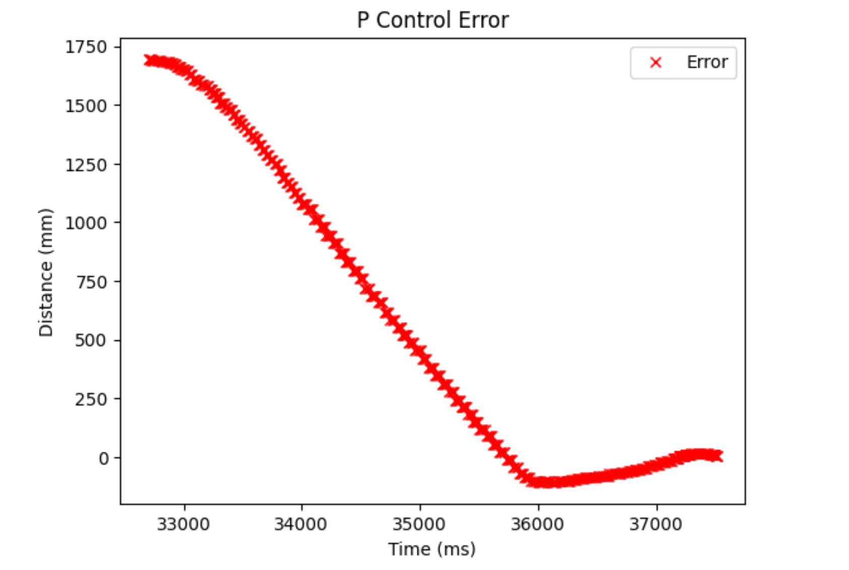
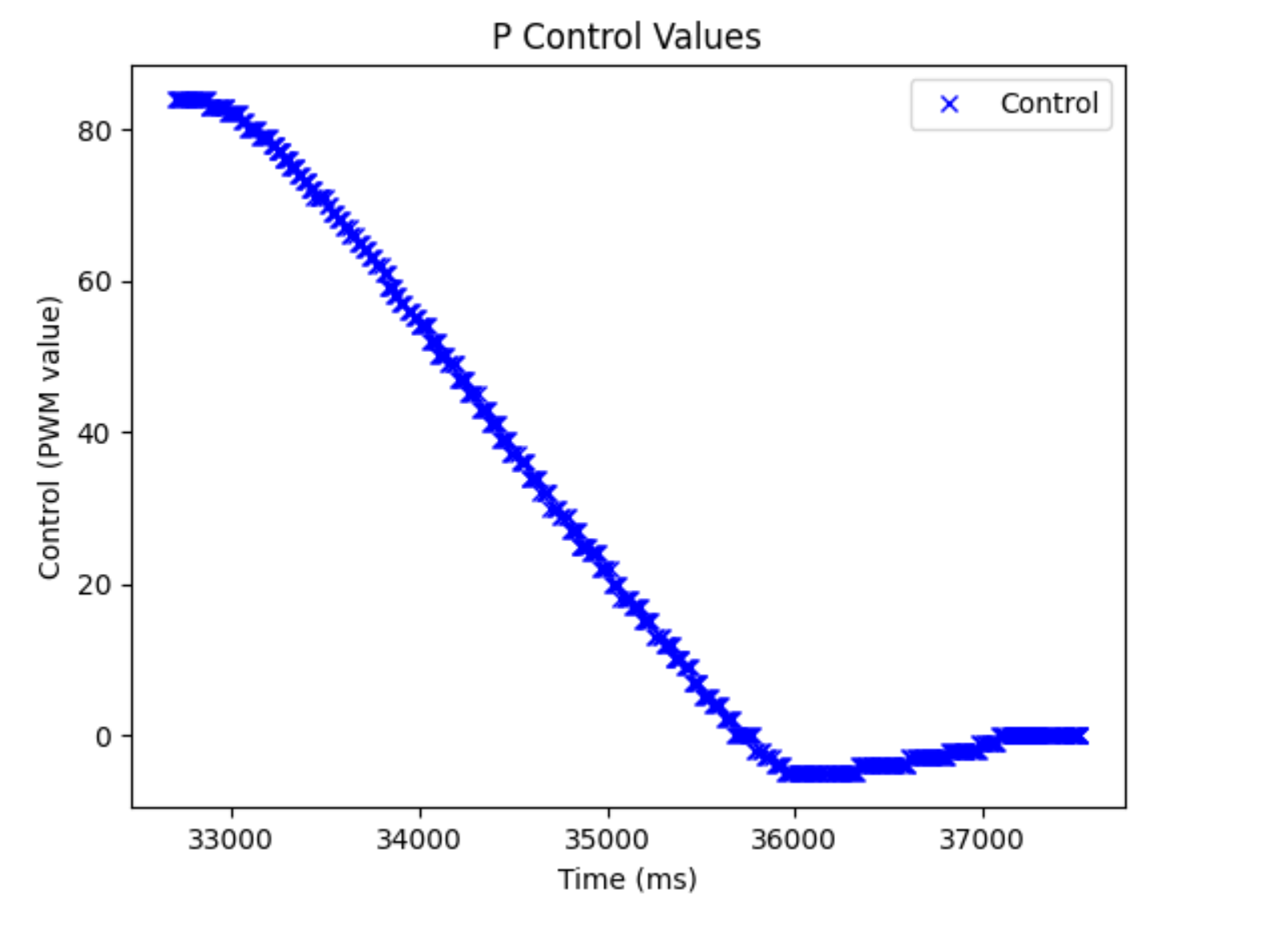
As we can see, it reacts pretty stably. I was able to hit a speed of 0.5 m/s (from looking at change in error/time elapsed data in Python) Some higher-values did work as well, but would would either crash or come close to the wall and I knew that when I added an integrator term, it would move even faster so I didn’t want to really use those values. As we can see, when we use a P controller, the control value only reacts according to the current error, causing the reaction to not be so fast. It works, but adding an integrator term would make it react faster if we start it further away, since it also scales our control term based off of accumulated error. I wanted my robot to move faster when it was further away, so I added an integrator term.
PI(D) Controller
An integrator term allows for the robot to move faster when the accumulated error is large, as we use this accumulated error to also . This means that if you have a more conservative Kp value, like I do with my robot, you can still have the robot move faster when it’s further away.It can also be used to adjust for steady-state error, which I don’t believe we have a significant amount of in this system. Here is the code for the PI controller:
void loop() {
  current_time = millis();
  float dt = (current_time - prev_time)/1000;
  prev_time = current_time;
  //Obtain error
  distanceSensor1.startRanging();
  float distance = distanceSensor1.getDistance();
  float error = distance - setpoint;
  float integrated_error = error * dt;
  if(a_error < 20000 || integrated_error < 0){
    a_error = a_error + integrated_error;
  }

  control = kp * error + ki * a_error;
  int speed = abs(control);
  if(control < 0){
    forward = false;
  }
  else{
    forward = true;
  }
  if(speed < 53){
    speed = 53;
  }
  if(speed > 255){
    speed = 255;
  }

  if(abs(error) < 10){
    stop_robot();
    a_error = 0;
  }
  else if(forward){
    go_forward(speed);
  }
  else{
    go_backwards(speed);
  }

}
I tested it many times to find some good values. Eventually, I landed on having a Kp of 0.05 and a Ki of 0.005 (because the accumualted error term can get pretty large pretty quickly). I also wanted to have a conservative controller, which I felt would eliminate the need for a D term as well. Here is a video of three attempts of the robot. The first two attempts are with the distance sensor in short mode and the third is in long:
And here are the corresponding plots for each run:
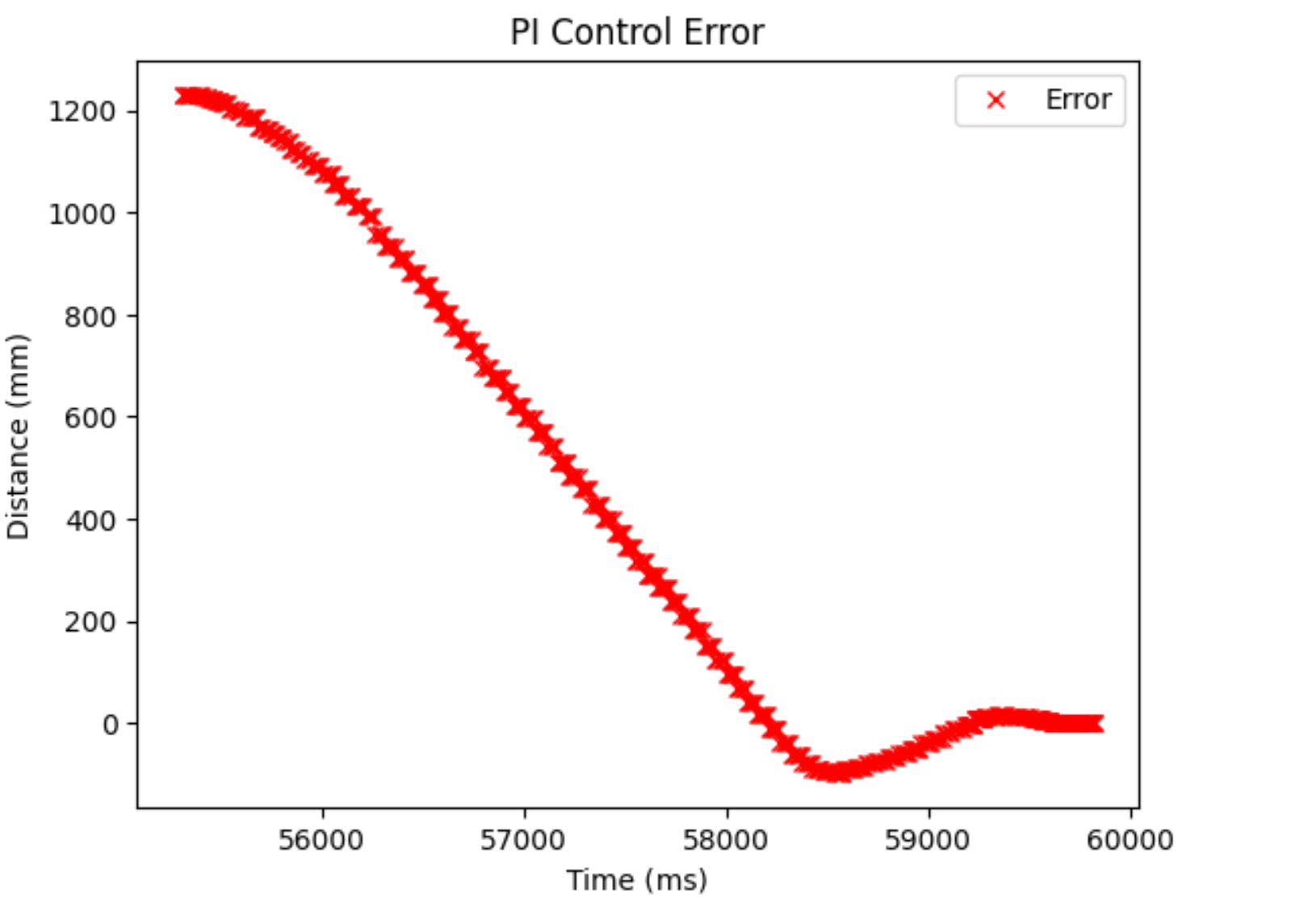
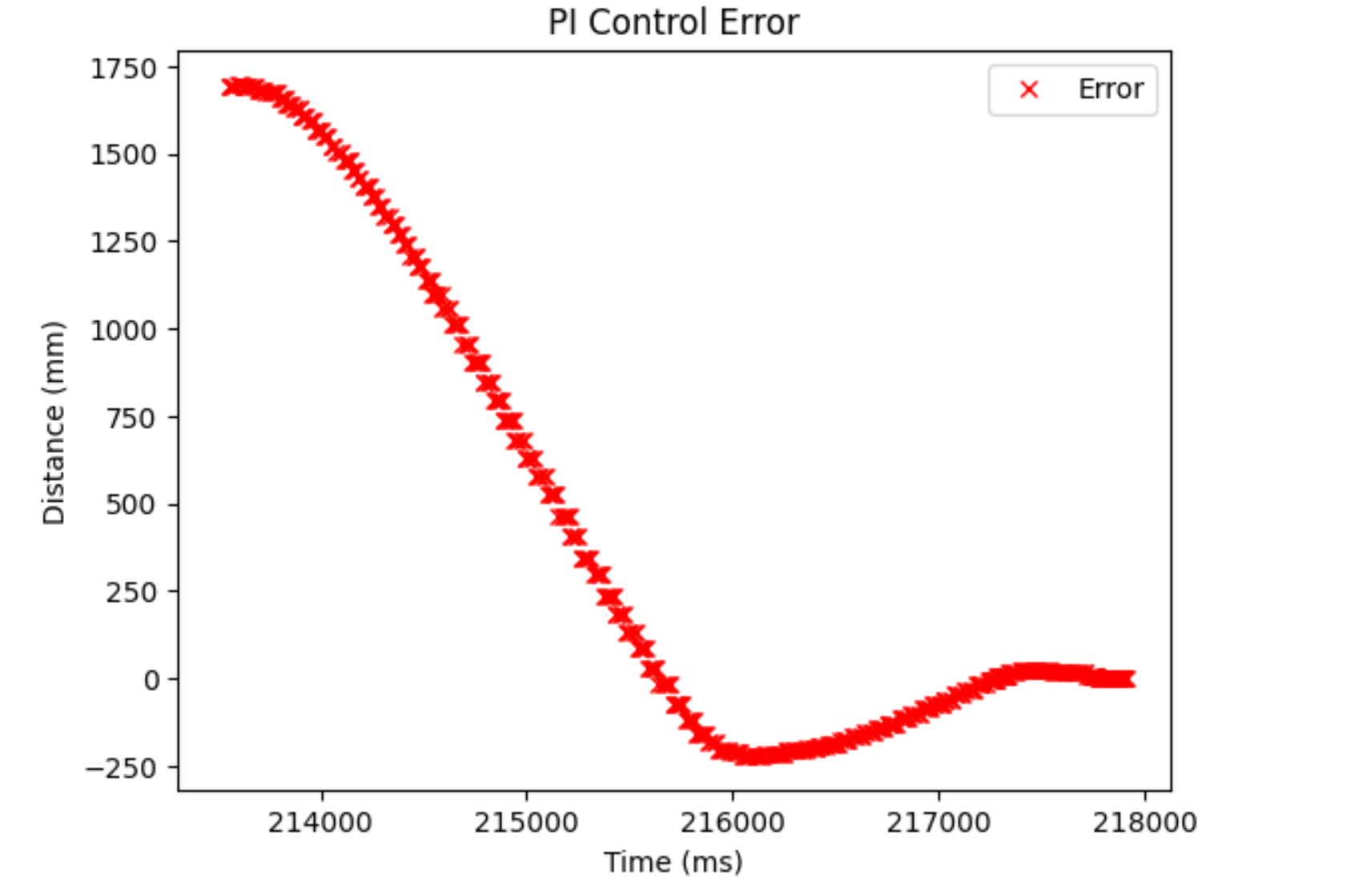
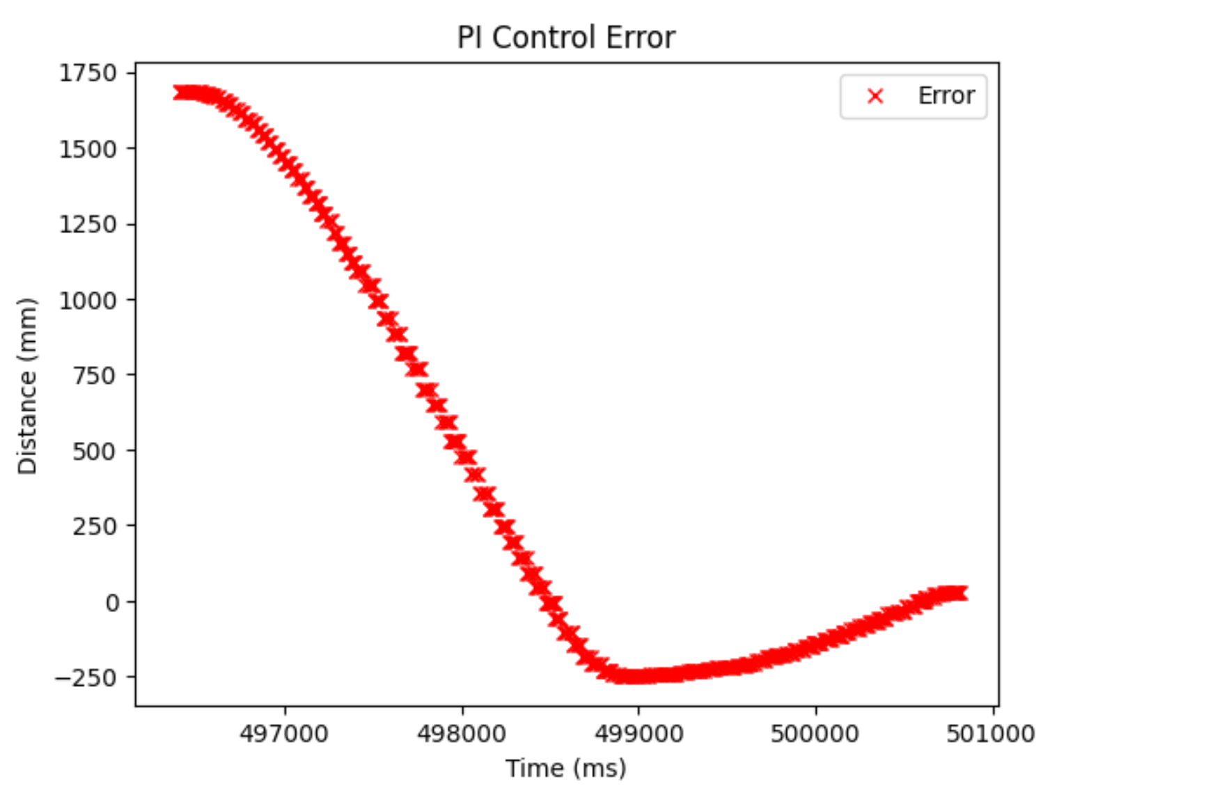
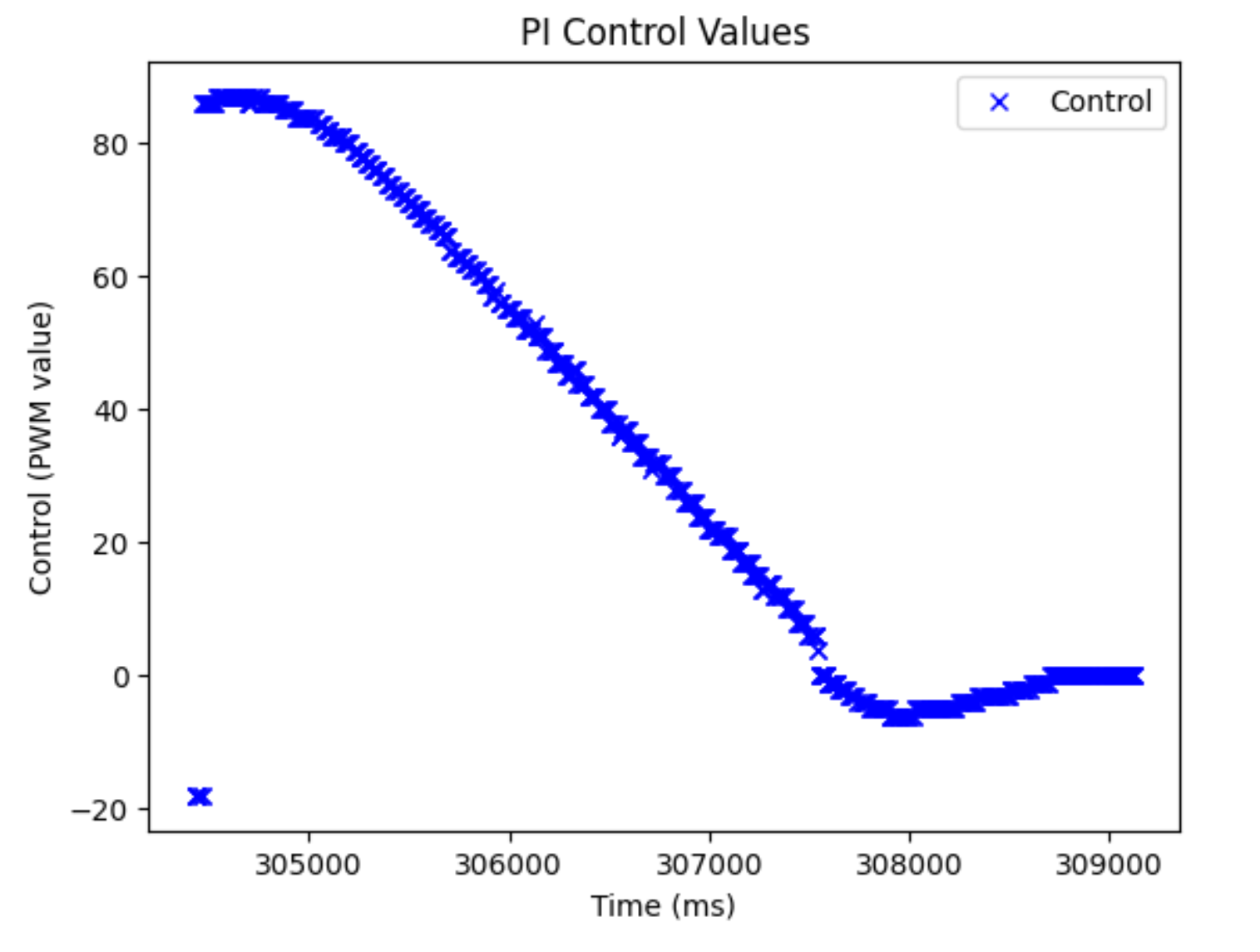
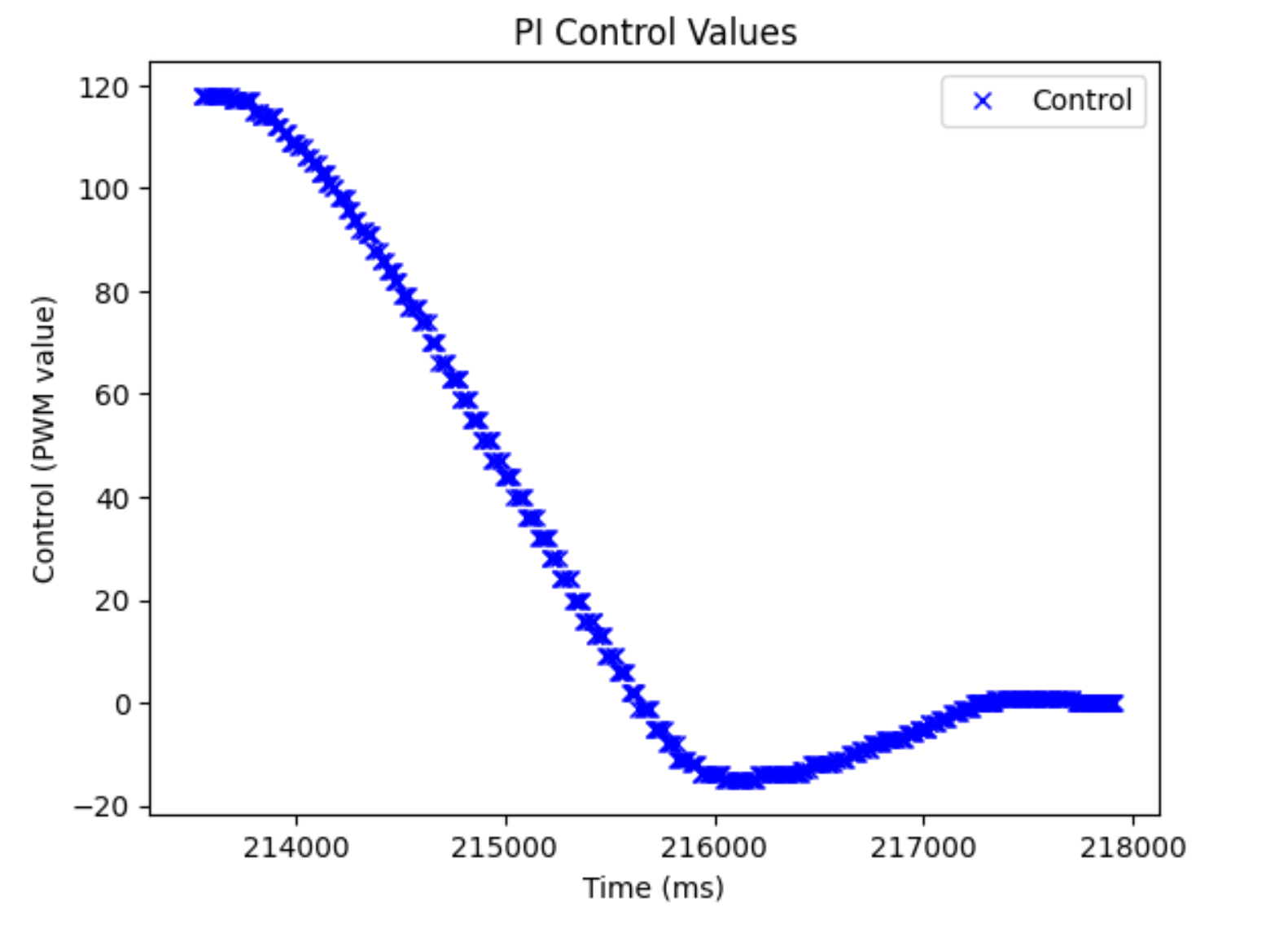
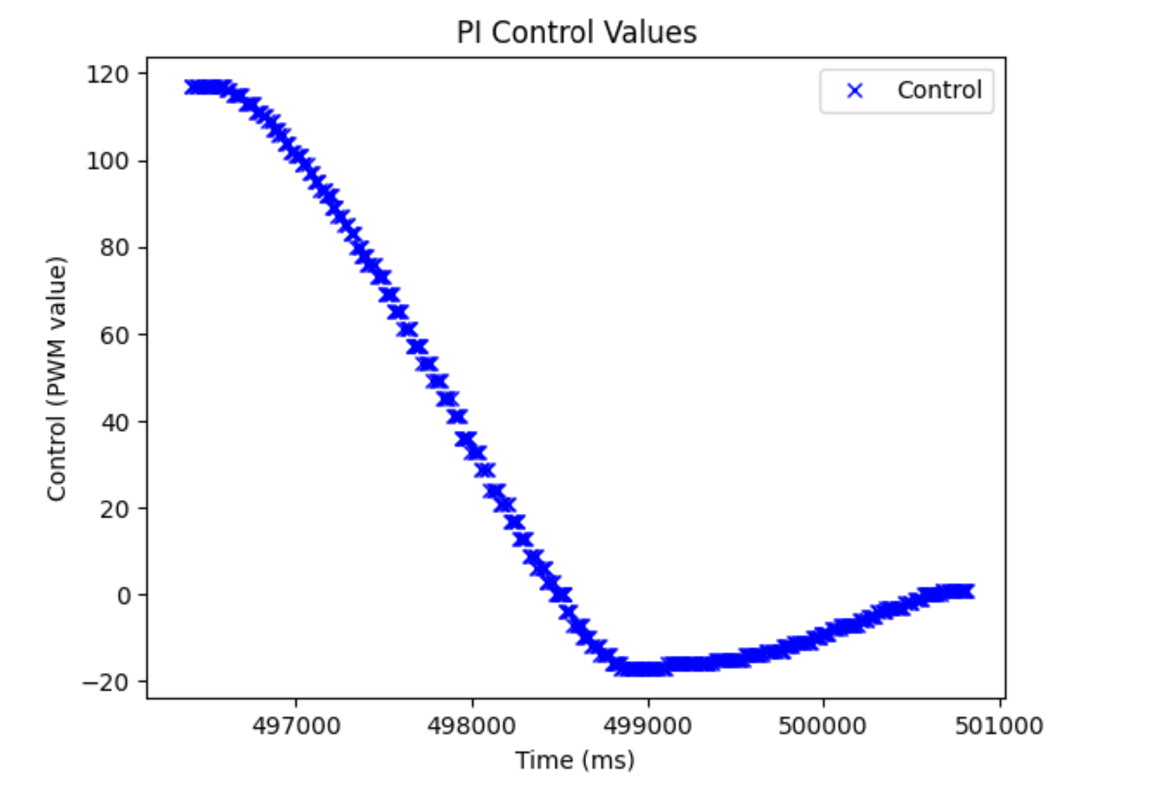
As we can see, the control values and error plots look different. We can see a bit of the hump in the control values, but because of the conservative nature of the controller, it isn’t really there. It’s more that the control values stay larger for a longer period of time and are also larger when placed further away, which both allow for the robot to move faster when placed further away. When I made the distance shorter, (1.5 m), I noticed it had a max speed of 0.6 m/s, which was still faster than the P controller further away. It hit a speed of ~ 1 m/s when I put it at the same distance (~2.1 m) that I used when testing the P controller.
MEng Task: Dealing with Integrator Windup
Integrator windup occurs when your integrator term becomes too large. This can occur when the system is not as reactive as you would like or when the robot sits still for a long period of time at steady-state (for instance, when my car stops after achieving its goal, error can still be accumulating because I have a grace period around the setpoint. Thus, if I leave it there for long enough, error can accumulate and start to shift my car). I decided to deal with this in two ways. First, I clamped my accumulated error term at 20,000, which is reasonable considering how fast error can accumulate (this makes it so that the Ki * a_error term will be the same as the Kp * error term if the error was 2000, which is about where I started my robot in these runs. Thus, I would get the equivalent of a proportional controller that is double the strength of my original P controller). I still allowed the system to add negative error at all times so that it wouldn’t become stuck at 20,000. The second way I dealt with accumulated error was to set the accumulated error term to 0 when my robot reached its goal. This meant that my robot would not accumulate more error while sitting still, but could still be reactive with its Kp term to perturbations like pushing the robot.